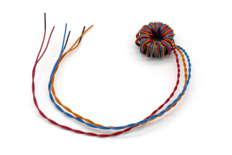
How are Gate Transformers Used in Tesla Coils?
Before we begin, let's first understand why we need gate transformers in modern double resonant solid state Tesla coils (DRSSTCs). The DRSSTC controller, or "brains" of the Tesla coil, is a low voltage circuit which has IGBT gate drive outputs which are low voltage and ground referenced to earth. The output of these IGBT gate drive circuits are typically +24V and are configured in a push-pull fashion. On the otherhand, the IGBTs in the half-bridge or full-bridge are floating at voltages up to 700VDC. If you directly connected the earth referenced control signals of the controller to the IGBTs in the bridge circuit, you would blow up both the controller and the IGBTs instantly in spectacular fashion!
Here are the two primary reasons that gate transformers are needed:
- Voltage Isolation - Because the controller is low voltage and ground referenced to earth and the IGBT bridge circuits are floating at high voltage DC and referenced to the AC line voltage, there needs to be electrical (galvanic) isolation between the controller and the bridge. The gate transformer electrically isolates the controller from the IGBTs and allows the ground referenced controller signals to safely control the high voltage floating IGBTs in the half-bridge or full-bridge.
- Voltage Translation - In some cases, a gate drive voltage is desired that is higher than what your controller is capable of providing. Using a gate transformer with a 1:2:2 step-up ratio, you could use a 12V controller gate signal to generate 24V gate signals on the secondary side of the gate transformer.
Building your Own Gate Driver Transformer
Building your own cascaded current transformer is incredibly simple. The first thing to do is obtain the parts required to build the current transformer which are shown in the list below:
Parts Required:
- Ferrite Core 77-1 - Use one of these cores for half-bridge based DRSSTC Tesla coils, such as our Reference Design 1.0 or Best 6.0 DIY Tesla coil. These gate transformers will have three (3) total windings.
- Ferrite Core 5000-1 - Use these larger cores for full-bridge based DRSSTC Tesla Coils, such as our Reference Design 2.0, Reference Design 3.0, or Best 12.0 DIY Tesla coils. These gate transformers will have five (5) total windings.
- 24 AWG Wire - This is the wire that will be used to wind the gate transformers. This wire is rated for 600V which is adequate for most DRSSTC Tesla coils. We recommend using 6 feet for each winding.
Winding your Gate Transformer
- Begin by cutting your 24 AWG wire in 6 foot lengths for each winding. If you have a half-bridge, you would cut three (3) pieces and if you have a full-bridge, you would cut five (5) pieces.
- Tie a knot in one end of the wires
- Secure the knot to the edge of a bench using a clamp or similar apparatus. Masking or duct tape can also be used.
- Pull the wire taut and tie a second knot in the opposite end of the wires.
- Insert the second knot into the jaws of a cordless drill. Pull the wire taut and then slowly operate the drill to twist the wires together. Twist until you have approximately one twist per inch. Do not overtwist as you could damage the wire.
- Remove the knot from the drill.
- Hold your core in one hand about 16" from the point where the first knot is secured to the bench.
- Winding 12 turns through the core making sure the turns are evenly spaced around the core.
- When you are finished winding the core, make sure both ends of the wires are approximately equal to length or the shortest is at least as long as your total winding needs to be external to the core.
- Make sure the turns are tight on the core and clamp the core using a vise or similar device. If your vise is metal or sharp, be sure to put something soft between the transformer and the vise to prevent the transformer from being damaged. Apply only light pressure to clamp the transformer.
- Hold the wires exiting the core vertically together and use wire cutters to trim all wires at an equal length to the length desired (typically 10"-16")
- If the wires are still twisted, untwist them and make them all straight.
- For all wires exiting the core on one side, mark the ends of these wires with permanent marker. This will be your phase markings. These black marks will denote positive phase for the windings on the transformer.
- Next, take each winding pair and twist them tightly together by hand to the very end of the winding. If your windings are all different colors, then you will be winding the two ends of wires that are the same color. If you have multiple windings of the same color, you will first need to use a multimeter set on continuity or resistance to determine which wires exiting the core are the same winding. Remember, you are twisting together the same physical wire as it was wound on the core.
- Do this for all windings on the core.
- Congratulations, you have now completed the build of your gate transformer!

