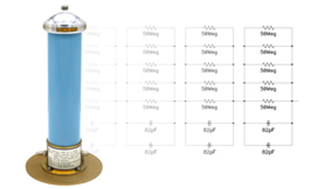
DIY your own 60kV high voltage divider using the plans and schematics featured here. This is a design of a wide bandwidth, 1000:1 high voltage divider capable of measuring high frequency waveforms to 50MHz. This high voltage divider is especially useful for measuring high voltage pulses or transients which contain high frequency components and works especially well for measuring Tesla coil primary circuit voltages.

Commercial 60kV High Voltage Divider
Theory of Operation
The function of a high voltage divider is very simple. Connect a high voltage signal at the input, and read a corresponding scaled version of the input voltage at the output of the divider which can safely be measured via a multimeter or an oscilloscope. The scaling factor of this particular high voltage divider design is 1000:1. This means that if you were measuring a 20kV input pulse, you would get a corresponding 20V output pulse at the output of the divider. This seems simple enough. Connect a large series string of resistors together and you have a 1000:1 divider. Does this work? Well, yes, if you only want to measure DC voltages. The problem is that the parasitic lead-to-lead capacitances of the resistors, and the distributed parallel capacitances of the resistors to ground ultimately kill the AC response from the high voltage divider.
Combined Resistive-Capactive Divider
To correct this issue, we must employ an equivalent 1000:1 capacitive divider scheme in parallel with the resistive divider network. At high frequencies, the capacitors work together to provide the proper voltage division while at low frequencies, the resistors work to provide the equivalent voltage division. However, if you looked at the frequency response of a resistive-capacitor divider itself, you will see that although the frequency response is flat near DC and flat at the upper end of the frequency band, the frequency response will dip in the midband frequencies. To correct this, a compensation network needs to be employed to correct this and to maintain a flat frequency response across the entire frequency range.
PSPICE Frequency Response Simulation
The following links show the PSPICE schematic and simulated frequency response of this high voltage divider design. From the PSPICE plot, you can see that the frequency response is flat from DC all the way out to the 3dB roll-off point at 54MHz. Now in practice, parasitics in your components, wiring, and layout will limit the overall frequency response and you won't get the theoretical 54MHz operation as predicted in PSPICE, but with the proper compensation, you will be able to get frequency response out to at least 10MHz.
Click here for the PSPICE simulation schematic (PDF)
Click here for the PSPICE frequency response plot (PDF)
High Voltage Divider Design and Schematic
The high voltage divider shown below is a field proven design and works extremely well. I have used this in several homemade high voltage dividers I have constructed and it worked especially well for measuring primary voltages in Tesla coils I have built. When building your own 60kV high voltage divider, choose 50Meg high voltage resistors rated for 10kV and at least 2 watts each. The 82pF capacitors should be rated for at least 10kV each. Potentiometer, Radj and the 25.3nF capacitor in parallel with Radj are used to calibrate the divider to an exact ratio of 1000:1. The compensation network between Radj and the BNC output connector corrects frequency response across the entire measuring band and may have to be tweaked accordingly depending on components being used in the upper divider stages as well as output cable being used.
Click here for the 60kV high voltage divider schematic (PDF)
This high voltage divider design has served me well over the years. As I mentioned previously, I have built a number of these dividers and they work well for measuring high frequency high voltage signals to at least 10Mhz. Enjoy!

